Neicytechno – VLAN configuration in Cisco Packet tracer, VLAN or Virtual LAN is a broadcast domain that is partitioned and isolated in a computer network. VLANs can create a functional view of network traffic across network devices where there is only one network that is physically visible but acts as if it is shared between different networks. VLAN is considered to be able to overcome several network management and security problems by using a network segmentation system based on VLAN numbers. Routers using VLANs filter network traffic, improve network security, perform address summary, and reduce network traffic congestion. Using VLANs, we can break up a large network into smaller independent segments.
how to Configure VLAN on Switch in Cisco Packet Tracer?
In its use, we can simulate the use of VLANs to break up large networks into small segments using the Cisco Packet Tracer. We will try with a simple simulation using a topology that is simple and often found around us.
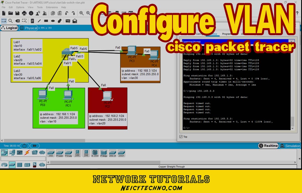
Case in point, there is 1 switch that will be used to build 3 LABs with different locations. We will provide IP addresses according to the lab used so that each IP address is not the same. By using VLAN we can make 1 switch into several network segments with specified interfaces. How:
Information;
we are using a cisco 2960 switch, where interface (int fa0/1-2) is vlan10, interface (int fa0/3-4) is vlan20, and interface (int fa0/5-6) is vlan30
first, we configure switch 2960, how to press the switch and enter the CLI tab,
Then we first check the VLAN connection and the interface on the switch, making sure the interface is active and the VLAN has not been configured. for that write the command Enable (to turn on the switch) and sh vlan (to see the status of the VLAN)
Switch>
Switch>en
Switch#sh vlan

VLAN Name                             Status    Ports
---- -------------------------------- --------- -------------------------------
1    default                          active    Fa0/1, Fa0/2, Fa0/3, Fa0/4
                                                Fa0/5, Fa0/6, Fa0/7, Fa0/8
                                                Fa0/9, Fa0/10, Fa0/11, Fa0/12
                                                Fa0/13, Fa0/14, Fa0/15, Fa0/16
                                                Fa0/17, Fa0/18, Fa0/19, Fa0/20
                                                Fa0/21, Fa0/22, Fa0/23, Fa0/24
                                                Gig0/1, Gig0/2
1002 fddi-default                     active
1003 token-ring-default               active
1004 fddinet-default                  active
1005 trnet-default                    active

VLAN Type  SAID       MTU   Parent RingNo BridgeNo Stp  BrdgMode Trans1 Trans2
---- ----- ---------- ----- ------ ------ -------- ---- -------- ------ ------
1    enet  100001     1500  -      -      -        -    -        0      0
1002 fddi  101002     1500  -      -      -        -    -        0      0
1003 tr    101003     1500  -      -      -        -    -        0      0
1004 fdnet 101004     1500  -      -      -        ieee -        0      0
1005 trnet 101005     1500  -      -      -        ibm  -        0      0

VLAN Type  SAID       MTU   Parent RingNo BridgeNo Stp  BrdgMode Trans1 Trans2
---- ----- ---------- ----- ------ ------ -------- ---- -------- ------ ------

Remote SPAN VLANs
------------------------------------------------------------------------------

Primary Secondary Type              Ports
------- --------- ----------------- ------------------------------------------After confirming that the interface is active and the VLAN is still empty, we can immediately create vlan10, vlan20, and vlan30 on the switch, with the command ..
Switch(config)#vlan 10
Switch(config-vlan)#name Lab1
Switch(config-vlan)#int fa0/1
Switch(config-if)#switchport access vlan 10
Switch(config-if)#int fa0/2
Switch(config-if)#switchport access vlan 10
Switch(config-if)#exit
Switch(config)#vlan 20
Switch(config-vlan)#name Lab2
Switch(config-vlan)#int fa0/3
Switch(config-if)#switchport access vlan 20
Switch(config-if)#int fa0/4
Switch(config-if)#switchport access vlan 20
Switch(config-vlan)#exit
Switch(config)#vlan 30
Switch(config-vlan)#name Lab3
Switch(config-vlan)#int fa0/5
Switch(config-if)#switchport access vlan 30
Switch(config-vlan)#int fa0/6
Switch(config-if)#switchport access vlan 30
Switch(config-if)#exit
Switch(config)#exit
command note;
- enable (privilage command)
- configure (Global Config mode)
- vlan 10 (to create a vlan 10)
- name Lab1 (to make vlan 10 name lab1)
- int fa0/1 (indicates the interface port to be used)
- switchport access vlan10(maps interface to vlan10)
- sh vlan (display vlan table)
The VLAN configuration process on the switch is complete, to ensure our configuration has been successful we can retrieve the VLAN information using the sh vlan or show vlan command.
Switch>en
Switch#sh vlan


VLAN Name                             Status    Ports
---- -------------------------------- --------- -------------------------------
1    default                          active    Fa0/7, Fa0/8, Fa0/9, Fa0/10
                                                Fa0/11, Fa0/12, Fa0/13, Fa0/14
                                                Fa0/15, Fa0/16, Fa0/17, Fa0/18
                                                Fa0/19, Fa0/20, Fa0/21, Fa0/22
                                                Fa0/23, Fa0/24, Gig0/1, Gig0/2
10   Lab1                             active    Fa0/1, Fa0/2
20   Lab2                             active    Fa0/3, Fa0/4
30   Lab3                             active    Fa0/5, Fa0/6
1002 fddi-default                     active
1003 token-ring-default               active
1004 fddinet-default                  active
1005 trnet-default                    active
it seems that each interface has entered its respective lab group. This indicates that the VLAN configuration on the switch has been successful. But to complete the Switch VLAN lab material, we have to set the connected computers according to the topology table in order to go to the final testing stage.
how to configure the computer ip address in packet tracer?
| PC | IP Address | Gateway | netmask | Vlan |
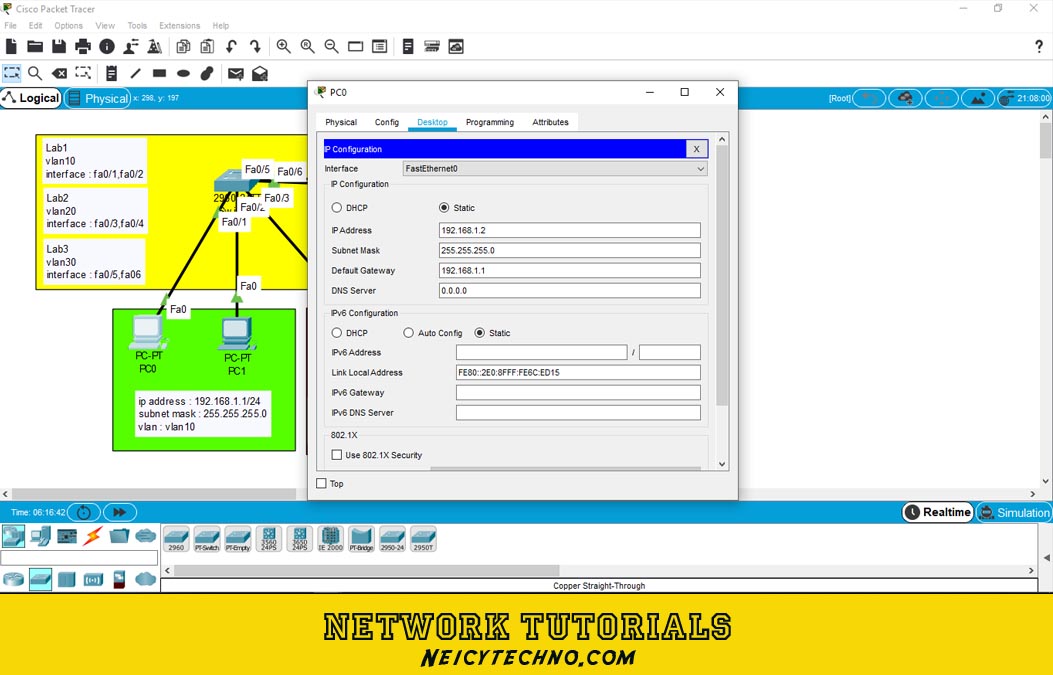
| PC0 | 192.168.1.2 | 192.168.1.1 | 255.255.255.0 | vlan10 |
| PC1 | 192.168.1.3 | 192.168.1.1 | 255.255.255.0 | vlan10 |
| PC2 | 192.168.2.2 | 192.168.2.1 | 255.255.255.0 | vlan20 |
| PC3 | 192.168.3.2 | 192.168.3.1 | 255.255.255.0 | vlan30 |
| PC4 | 192.168.3.3 | 192.168.3.2 | 255.255.255.0 | vlan30 |
The table above is the information that must be followed according to the topology. Adding an IP address on each computer can be done by selecting one of the PCs to be set and then going to the desktop tab — IP Configuration. And fill in the IP address information on each PC according to the topology table above.
Do the same steps on each PC according to the topology table.
Final VLAN Configuration Test
To test whether the VLAN configuration in the lab has been successful, we can do several ping tests on computers that are in the same VLAN (lab) and on different VLANs. By using the Command Prompt provided on each PC in the “Desktop — Command Prompt” tab.
- Ping from PC0(192.168.1.2) to ip address PC1(192.168.1.3) will work and display status “reply from 192.168.1.3” which means both pc in the same lab can be connected to each other.
- do a ping from PC0(192.168.1.2) to the ip address PC4(192.168.3.3) it will work and display the status “request time out” which means it can’t connect.
ping (destination ip address)
Then the result will be, PCs in Lab1 cannot be connected to PCs in other Labs (Lab2 & Lab3) and vice versa. Each PC can only connect with PCs in the same VLAN or in the same Lab.
